 |
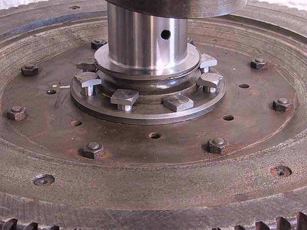
With the flywheel face down on the work bench, the crankshaft is fitted into the centre hole and the bolts gently tapped into place. The bolts are an interference fit so may not fully bed down at this point. Ensure that the heads sit against the abutment. Take care that the oil scroll is not damaged during this procedure. |
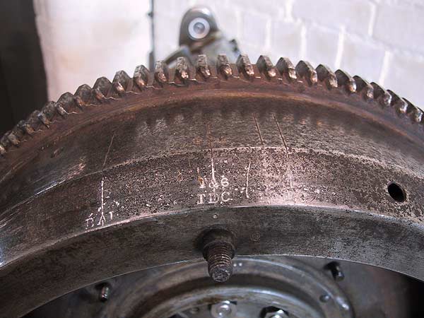 |
On initial assembly it is obviously important to make sure that the TDC marking for pins 1 & 6 are aligned with the crankshaft. It is worth cleaning the flywheel markings with a brass brush. The markings have been painted with liquid paper (Tipex, etc) and the excess wiped off so that all valve, timing and positional stampings will be clearly visible when the engine is assembled. |
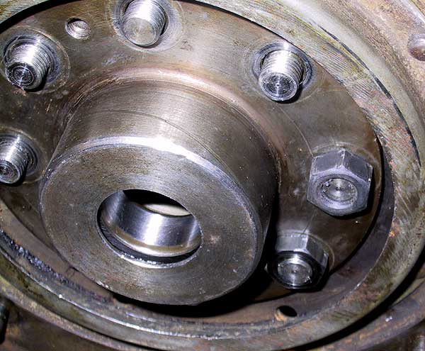 |
The bolts need to be pulled fully into their seats using a standard bolt. This method obviates damage to the correct narrow bolts. This picture shows the difference between a normal 3/8" nut (upper) and the correct item. Thin nuts with short bolts were used on all Small HP R-R flywheels up to the end of series F2. |
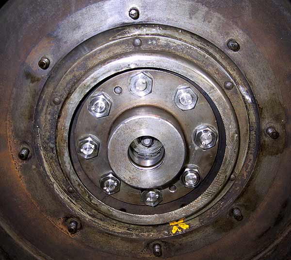 |
The correct nuts were fitted and then tightened by 'feel'. Afterwards, they were all checked with a torque wrench. There are no torque settings for pre-War engines: all nuts were found to read 45 lbs/ft, which seemed reasonable. The ends of the bolts have been centre-punched to flare the threads, which should remove any chance of the nuts working loose. The nut visible inside the support-bearing housing is the retainer for the rear sludge trap cap. |