 |
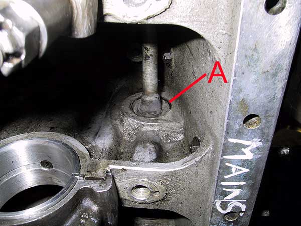
A view of part of the oil gallery. The brass inserts ('A') are an interference fit in the bearing web, are cross-drilled to feed the main bearings and are interconnected by soldered copper pipes. After cleaning the pipe interior it was pressure tested to ensure good sealing of the soldered joints and where the inserts located in the webs. This was achieved by part-filling the pipe with cleaning fluid, blanking off the outlet drillings in the casting and then blowing compressed air in from the rear plug. Not surprisingly, it was found that numbers 4 and 7 inserts were leaking. All insert joints were cleaned and sealed using an anaerobic bearing solution (Truloc 211) on both front and rear faces. |
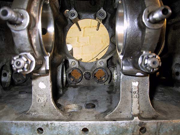 |
Looking up inside the crankcase at #4 cylinder aperture. Note that the 4 head studs are screwed into extended bosses in the casting. Between the two tappet guides is a pinned nut, which locates the short stud that acts as both tappet bridge and block clamp. The stamped markings are clearly visible on the two bearing webs: - 4V26 and 5V26. These marks are common on all position- and rotation-dependant components. |
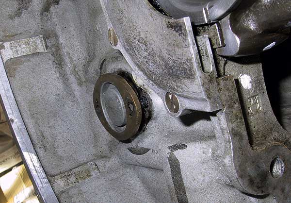 |
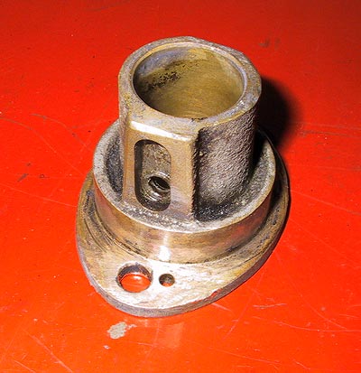
Looking sidewards at the clutch housing; showing the partially removed rear cam bearing. Interestingly, the bearing is stamped with both the part number and the engine number (E8L). This bearing is an interference fit in the casting. Removal should not be attempted by levering the flange as this will merely cause distortion. |
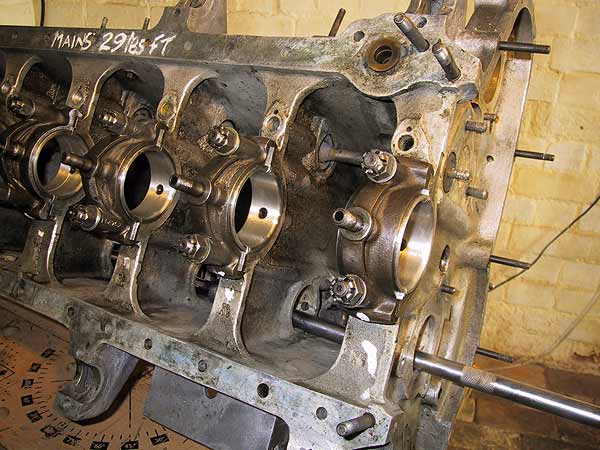 |
The safest removal method is to use a long bar with a smooth, flat face that is slightly smaller in diameter than the cam journal. Care is needed to avoid damaging the bearing. |
 |
Number 7 cam bearing viewed from the top. Without removal it is highly probable that the tiny oil sump and feed hole will remain clogged with debris. |