|
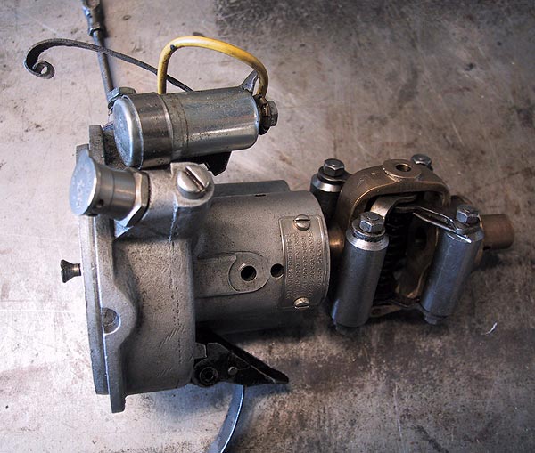
Removal of the distributor is straightforward. Release the cap and move aside. Remove the magneto HT lead from its socket. Disconnect the control lever. Undo the four retaining nuts and washers from the flange. The distributor body pulls out. It will be sensible to remove the drive collar from the drive gear and clean out the cavity. It will be seen that the drive collar has one double tooth to ensure that everything goes back in the same alignment. It will be necessary to re-time the ignition after rebuilding the distributor. |
 |
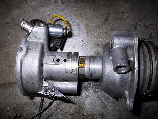
Remove the rotor arm, undo the set screw in the points cam, tap the side of the cam with a wooden screwdriver to release the taper and take the cam out. The is a set screw on the side of the body, above the label: remove it. The two halves of the distributor can the be parted as shown here. |
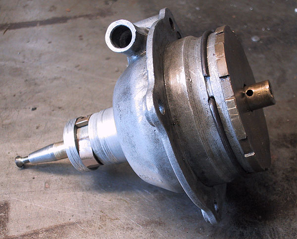 |
This picture shows the base of the distributor after removal of the drive pinion. The pinion is held on the shaft by a parallel, notched brass pin that must be driven out with a pin punch. The pin should have a centre punch mark one end; knock through from this end. The problem with this distributor was that the bottom of the shaft could be moved from side to side by a noticeable amount, which meant that the points were being opened by varying amounts dependent on the pinion load. |
 |
After removing the circlip the base plate unscrews (right hand thread). The pinion and pin are also shown here. |
|
|
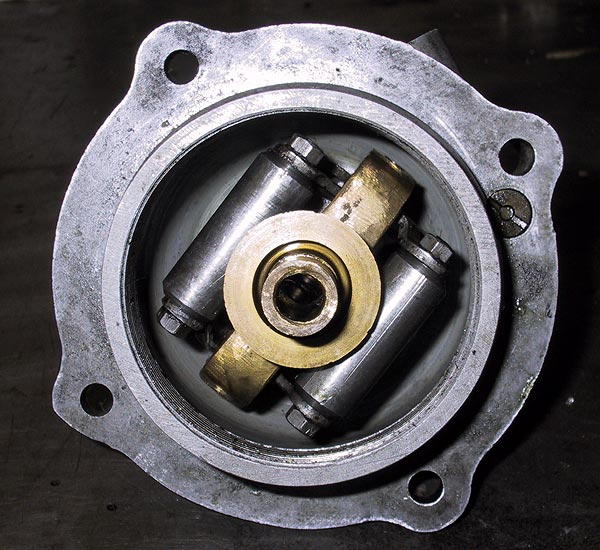
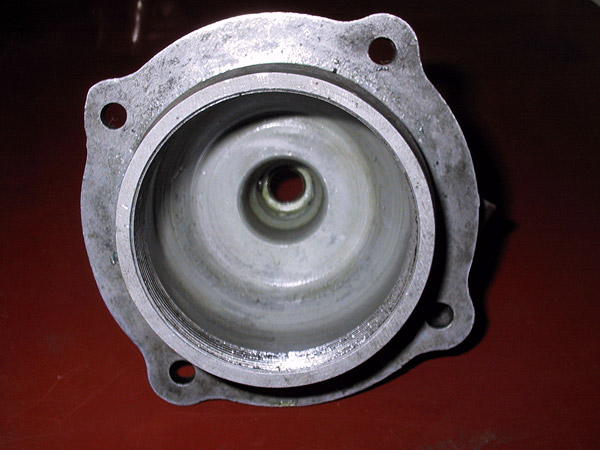
A view from the bottom showing the centring bush and governor weights. |
 |
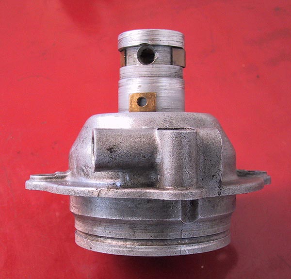
Replace the cam set screw in the top of the shaft and tap the shaft through the bearing to remove it from the case. Note the two brass collars. The larger collar acts as a spring to prevent lateral movement. The small rectangular piece accepts the set screw that holds the upper and lower body parts together. The screw has an extended nose that passes through this piece of the collar and regulates the extent of rotation by jamming against the sides of the enlarged hole in the body of the casting. Note the bush in the upper orifice that should be a sliding fit with the brass upper section of the governor tube. |
 |
Looking into the base of the upper body half after removal of the governor. |
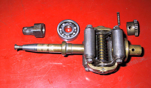 |
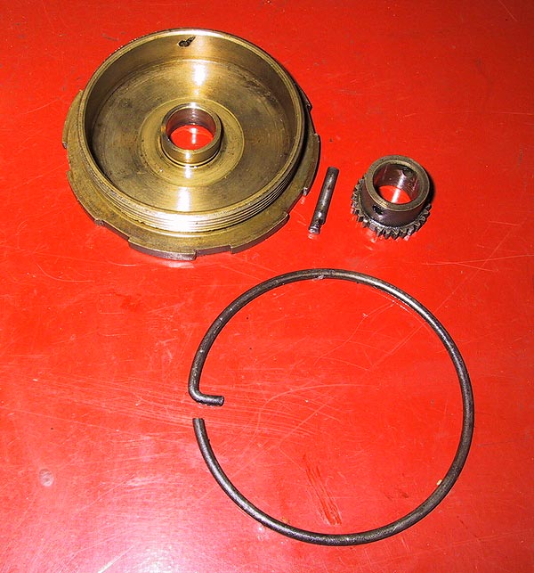
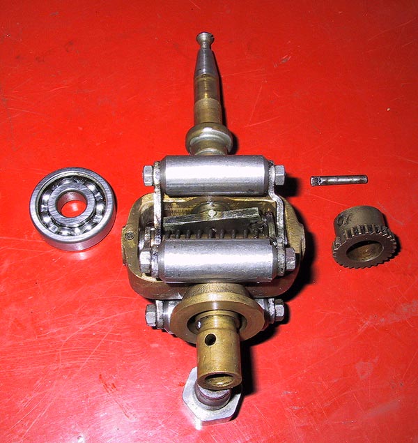
The governor parts, from left to right: - Points cam Ball race that fits in the upper body half. Cross pin and pinion - note the double tooth. The complete governor with set screw in the end of the shaft. The collar in the brass outer tube is the abutment for the base of the bearing that ensures vertical alignment. |
 |
The governor consists of an external tube attached to the bob weight frame with a central shaft that carries the points cam. As engine speed increases the weights are thrown outwards against the tension of the coil spring. The effect can be seen by pressing the weights together by hand. |
 |
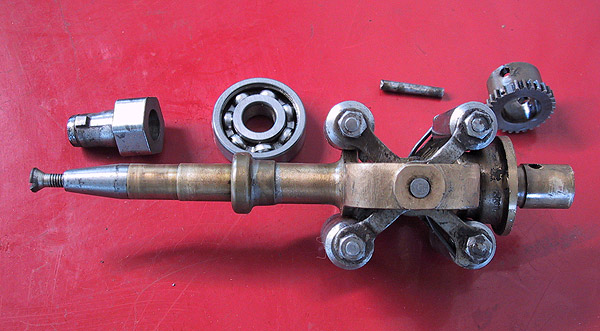
There is an angled plate visible between the weights that is connected by a cross pin to the shaft and by notches and lugs to the arms that hold the weights. As the weights move outwards the plate is moved, which twists the steel shaft to effect the advance of the ignition timing. All pivot pints should be inspected for wear, the spring should be undamaged and the tube and shaft should twist freely when the weights are moved. Any irregularities should be rectified. Dismantling is achieved by removing the cross-pins removing the parts from the frame. Note that the studs on the weights are peened over the nuts. Careful filing is required, if the weights need to be taken off their support arms, to avoid damaging any of the threads. |
 |
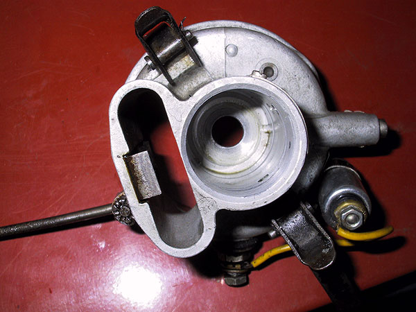
Showing the rectangular collar piece removed from the slot to reveal the enlarged hole that regulates the rotation of the upper section of the body. |
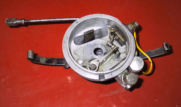 |
Top view of the upper body section after removal. Note that the points can be left in place. |
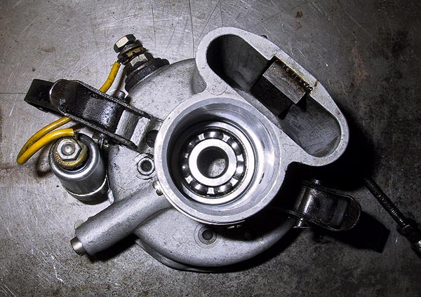 |
Upper body section viewed from underneath. The ball race can be tapped out from above using a drift and hammer. Despite the bearing being clean and smooth it had evidently worn to the point where it no longer held the governor shaft in axial alignment. |
 |
Bearing removed. The oil feed from the Rochdale cup can be seen at 3 o'clock. The replacement bearing is easily tapped into position. Do not be tempted to use a modern sealed ball race because the governor mechanism, beneath, relies on the oil dribbling from the bearing to provide its lubrication. |
 |
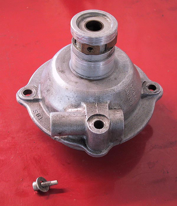
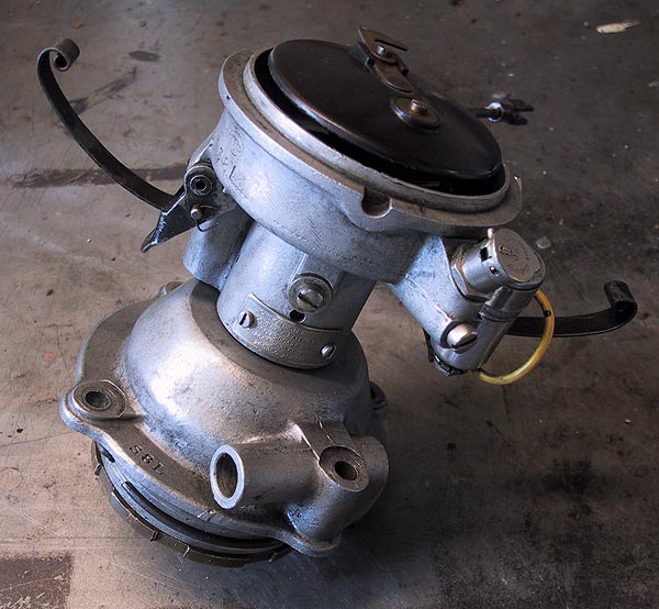
This is a demonstration photograph to show the relative position of the governor to the upper body piece. Obviously, the governor has to be assembled in the lower section of the distributor case. |
 |
Re-assembly is the reverse of the dismantling procedure. Lubricate the moving parts of the governor with engine oil before assembling. The governor is replaced in the lower case, tapping the shaft fully home against the bearing stop. The base plate, circlip and drive pinion are installed first. The end of the pinion cross pin should be centre punched to ensure that it will not work loose in service: It is worth applying an anaerobic stud adhesive for good measure. When mating the two halves it will be necessary to squeeze the larger collar piece to allow it to pass inside the upper case. After fully engaging the parts the set screw should be installed. |
 |
And back to the beginning. After replacing the distributor on the engine it will be necessary to re-time the ignition in the usual manner. |