Rolls-Royce 20/25 - engine
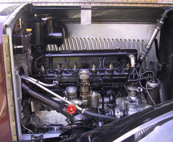 Offside view of the engine - Rolls-Royce variable jet carburettor in the
centre. The fuel mixture passes through a tube in the water jacket to reach the inlet
manifold on the nearside. Piping above the steering column is the supply and return to the
heater mounted under the dashboard. The box on the bulkhead is the electrical distribution
and fuse board. Above the engine, with the chrome filler cap, is the oil reservoir for the
chassis lubrication system. On the far side is the Autovac - an early form of fuel pump
that utilises the induction system depression to draw petrol from the tank, at the rear,
into its header tank.
Offside view of the engine - Rolls-Royce variable jet carburettor in the
centre. The fuel mixture passes through a tube in the water jacket to reach the inlet
manifold on the nearside. Piping above the steering column is the supply and return to the
heater mounted under the dashboard. The box on the bulkhead is the electrical distribution
and fuse board. Above the engine, with the chrome filler cap, is the oil reservoir for the
chassis lubrication system. On the far side is the Autovac - an early form of fuel pump
that utilises the induction system depression to draw petrol from the tank, at the rear,
into its header tank.
Return to previous page
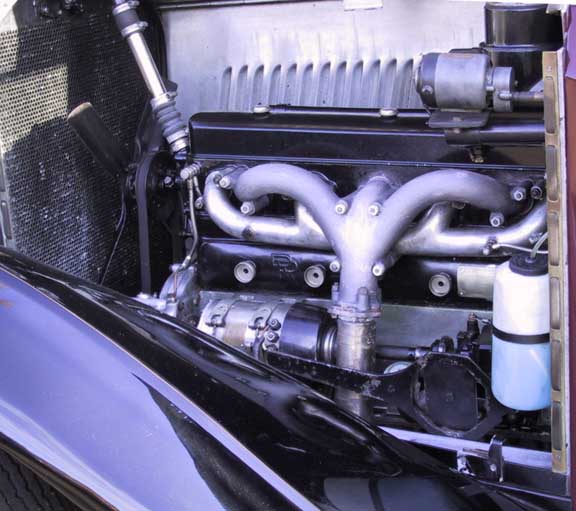 Nearside view with the manifolds dominating the picture.
Beneath the manifolds, located by the knurled knobs, are the tappet chest cover plates. To
the left of the exhaust is the dynamo. The drive shaft running behind the exhaust pipe can
be connected to operate the magneto in the event if ignition coil failure. The wheel
spanner is visible on its mounting bracket in front of the exhaust.
Nearside view with the manifolds dominating the picture.
Beneath the manifolds, located by the knurled knobs, are the tappet chest cover plates. To
the left of the exhaust is the dynamo. The drive shaft running behind the exhaust pipe can
be connected to operate the magneto in the event if ignition coil failure. The wheel
spanner is visible on its mounting bracket in front of the exhaust.
Return to previous page