Rolls-Royce 20/25 - sludge traps
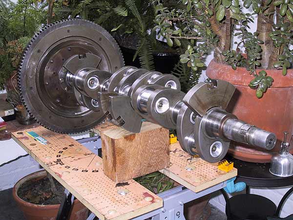 |
Crankshaft out of the engine and onto a work bench. Where better to work than amongst the verdant splendour of a conservatory? From this angle it is possible to see the balance weights, sludge traps and, at the nose of the crankshaft, the coarse splines for driving the damper |
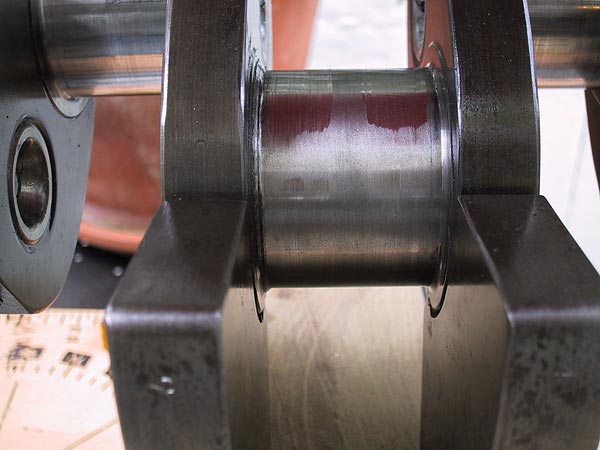 |
All of the journal surfaces were measured for ovality and taper. This necessitates taking at least 4 diametric measurements at 3 positions on each pin. For the rear, centre and front position on each pin the measurements are taken in the '+' and 'x' planes. With the exception of main journal #4, shown left, the measurements tended to be within 0.0003" with 2 or 3 extending to 0.0005". (That is, a maximum wear in oval or taper not exceeding one half of one thousandth of an inch - pretty good!) Number 4 is interesting (read expensive) and is deserving of further investigation. The centre section (under the oil supply and bearing groove) shows a ovality of 0.0024". The 2 wear patterns extend over only roughly 120 degrees and have a minimum diameter of 2.1214" - or 0.0031" below nominal. There is no visible or measurable wear on the opposite face of the journal. This leads to several observations: -
The shaft will have to be jigged and measured to ascertain the problem and indicate the cure. |
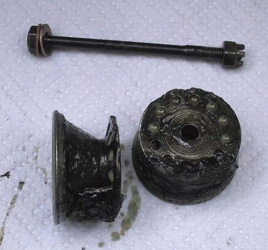 |
Despite the generally clean appearance of the engine's internals, this is a representative example of a big end sludge trap. The mains were basically clean. The debris has the consistency of oily soil. The deposits were positioned at the outer sides of the traps. An interesting observation is the pitting on the surfaces and the inner lips of the caps. This chassis had a 'resting' period (as our thespian cousins would have it) between the late 1950's and early 1980s. One must assume that this damage, along with the block corrosion, took place during this period. It is fortunate that the sealing faces survived in good order.
|
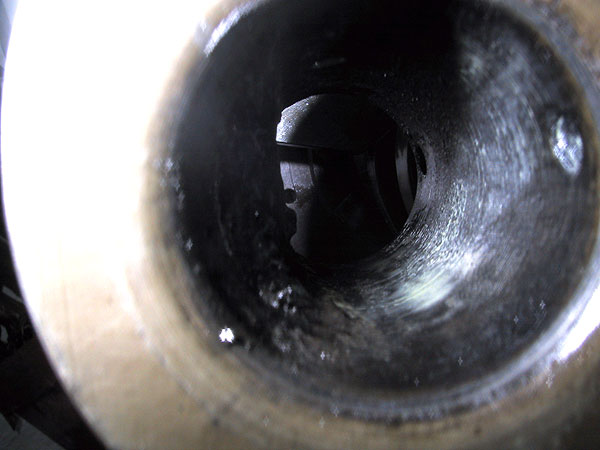 |
This is what happens when you try to be clever with a camera - near abject failure. It is very difficult to light inside the sludge trap whilst taking a picture from 2 inches away. The general idea will be self evident. Oil supply drillings on the right; crankshaft web and weight at the far end; the silhouette of crud on the left wall. Be warned. |