Rolls-Royce 20/25 - water pump drive
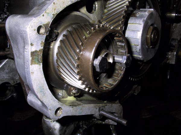 |
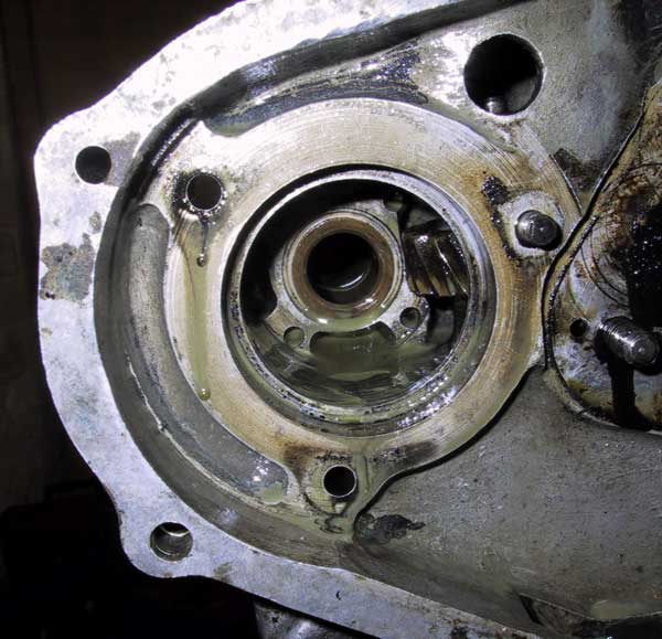
The shaft nut has been removed, as have the serrated end plate, spring and shaft. The serrated nut that holds the pinion in place had been replaced with a hexagonal nut of the same thread. This has been removed. This photograph shows how the pinion should be removed. 2 x bolts (1/4"BSF) are inserted in the 2 holes inside the pinion. The bolts should act against a forcer ring located between the rear of the pinion and the front of the bearing. They didn't. Guess what is missing. Whoever last re-assembled this component failed to replace the forcer ring. The bolts were trying to distort the ball race.
|
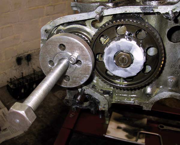 |
What should have been a two minute job extended into several hours. Having eventually identified that the forcer ring was missing it became necessary to devise an alternative cunning plan. This crude looking tool is a multi-model rear axle driving dog extractor. After careful measurement, two extra holes were drilled in the plate. Threaded rods were attached to the pinion and the centre bolt applied pressure against the end of the pinion spindle. The relatively odd position of the new holes was dictated by the position of the only visible datum line on the face of the disk. A frustrating waste of time. Gave up for the day. |
 |
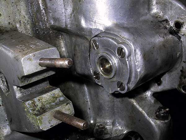
The pinion and bearing case have been removed. It is necessary to remove the idler gear to gain access to the right hand stud of the case. When assembled properly, the forcer ring should be interposed between the pinion and case. |
 |
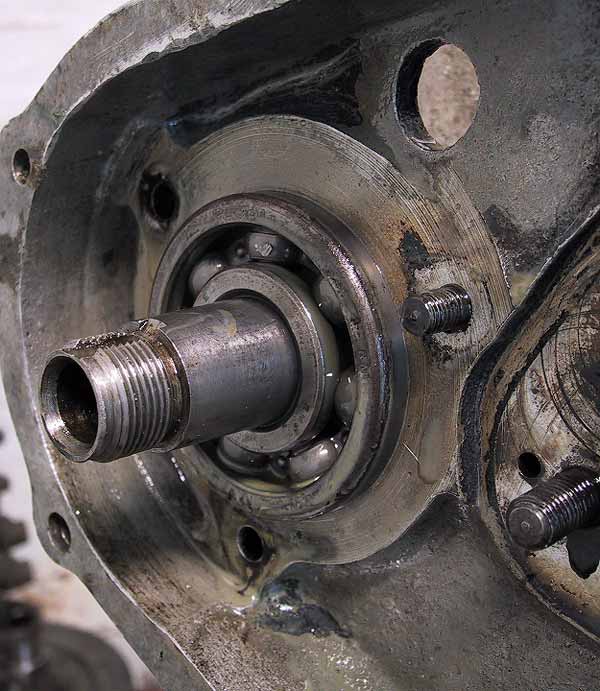
The water pump drive spindle viewed from the rear. The rear of the spindle incorporates an oil scroll to draw any excess oil back into the wheel case. The spindle is removed by drifting forwards. This action takes the bearing with the spindle. It is important that the oil pump drive shaft is free to rotate because the skew gears mesh inside this housing. |
 |
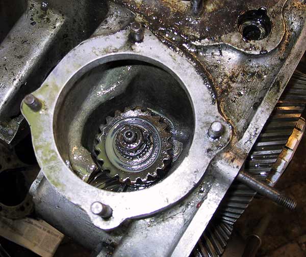
Viewed from the front and showing the rear support bush for the spindle. The oil pump / distributor drive shaft skew gear is visible on the right.
|
 |
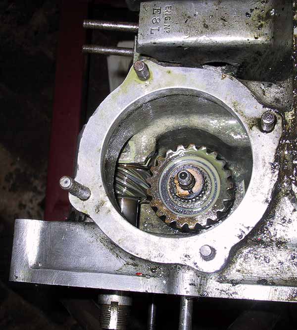
The oil pump / distributor skew gear viewed from above and showing the lock nut. Note that this shot was taken before the water pump shaft was removed.
|
 |
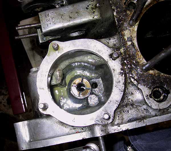
Lock nut removed. The serrations around the shaft are to locate the distributor drive collar. |
 |
The skew gear must be removed using a small bearing extractor. There should be a metal shim under the gear inserted to adjust the backlash. Care must be exercised to ensure that the shaft does not fall on the floor when the taper is broken. The lower bearing races are free to slide on the shaft as it is removed - ensure that they do not part and spill the balls all over the floor. |