 |
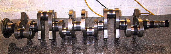
All main journals and big end pins were cleaned off and then had the oil holes sealed off with electrical masking tape. Now why would he do that? |
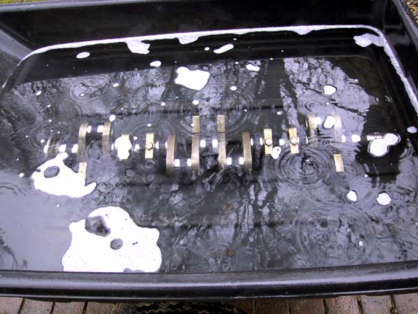 |
The crankshaft was submerged in a garden barrow filled with clean water and detergent. The latter ingredient was to reduce any surface tension on the crank surface. The exercise was to determine whether any of the sludge traps or bolts were leaking. Water ingress would have been evidenced by bubbles leaking from any aperture. Fortunately, the shaft was completely sealed. After about 10 minutes observation the crank was removed, dried and coated in WD40. |
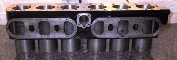 |
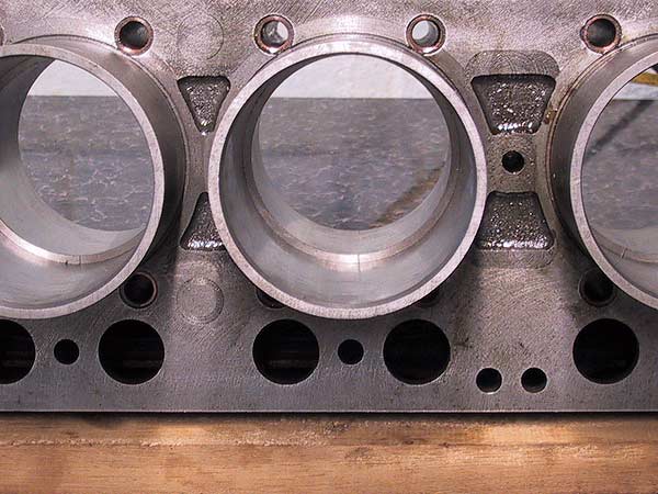
The new cylinder block - front to the right. Note how the cylinders protrude downwards inside the crankcase. |
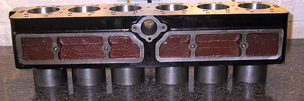 |
A near side view. The red oxide paint is to seal the casting to prevent any residual kinetic sand washing into the sump. |
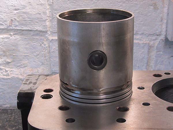 |
One of the pistons is use to set each piston ring square in the bore. The rings are positioned roughly at their top and bottom locations. |
 |
Rings positioned at the top of the bore. Original specifications for ring gaps were exceedingly tight: varying between 0.006" and 0.010". Having consulted with both the piston manufacturer and ring supplier it is evident that modern practice is to allow between 0.005" and 0.007" per inch of bore diameter. Some of the rings had to be swapped about but the end result was that all rings were gapped at between 0.019" and 0.024" |
 |
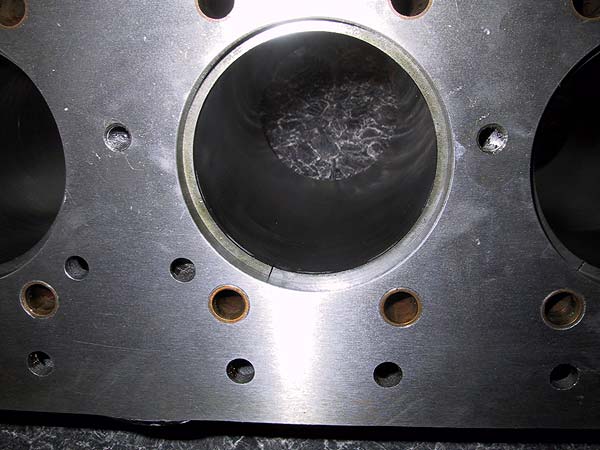
Rings positioned at the bottom of the stroke. Note that the ring position is only half way down the bore. These bores have been machined parallel. |