 |
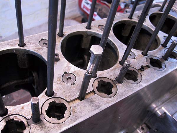
All head studs were checked to ensure that they were fully located and tightened in the crankcase: 5 were loose. To avoid twisting the studs it is good practice to only apply torque at the base. Marks are visible higher up the stud shanks from earlier tightening. |
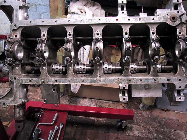 |
Camshaft inserted in the block and the bearings #2 through #6 have been screwed together around the journals. All journals were treated with assembly paste to ensure adequate lubrication when the engine is eventually started. As shown here the bearings are upside down so that the machine screws can be done up. |
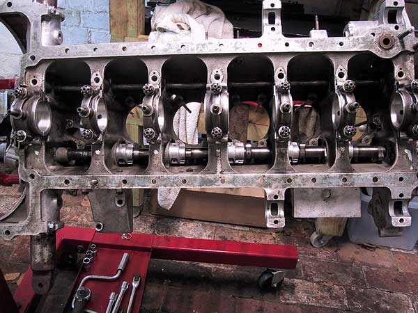 |
The bearings have been rotated on the shaft ready for knocking into place. Care is needed to ensure that the dowel sockets are aligned with the drillings through the block face and webs. The bearings are knocked into place a little at a time, each in turn, the camshaft being pushed further into the block and then the process repeated until fully home. Accurate positioning is confirmed by looking down the dowel holes from the upper face of the crankcase. This is one of the more 'agricultural' procedures used in the reconstruction. |
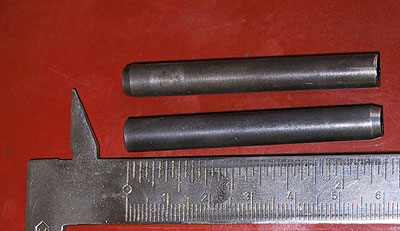 |
Two of the cam bearing dowels. The lower end is chamfered to aid location; the upper end is threaded 1/4" BSF to allow for extraction. The dowel length is 2.375"; the depth from the crankcase face into the base of the bearing socket is 2.437". |
 |
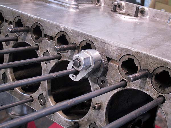
Using the threaded section, with bolt inserted, to tap the dowels into place. To the right is number 5 dowel already in place; it can be seen that, when fully home, the dowel sits 1/16" below the upper casting face. Before installing the dowels it is important that the bearings are correctly aligned. Where inspection shows that the sockets are not perfectly aligned it will be necessary to partially extract the bearing, rotate it and then knock it back home. Failure to do this will result in either damaged dowels or bearings that are not fixed in position. |
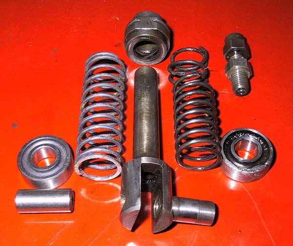 |
Cam follower / tappet. To the left are the new spring, wheel and axle; to the right are the broken #4 spring and damaged wheel. The spring is released by unscrewing the push-rod socket. All of the tappets were fitted with new springs and two needed a new wheel and axle. The axles are an interference fit and are extracted and replaced using a hammer and drift. |
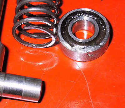 |
Close-up shot of one of the damaged wheels. This engine had been left unused for many years during the 1960s and 70s. This corrosion damage, both to the rim and wearing surface, undoubtedly happened during that period. |