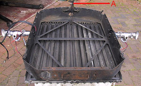
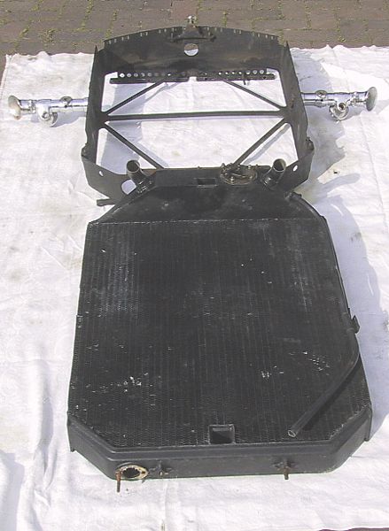
The inner shell following the removal of the radiator matrix. The two levers shown at 'A' are the items actuated by the calorstat to open the shutters. Prior to removing the core it is necessary to:-
1) remove the pivot pin
2) remove the small nut and bolt used to hold the two levers together as it will not pass through the aperture in the header tank.
3) remove the two small link plates that sit between the levers. (See below)
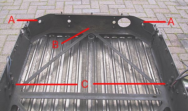
Looking at the base of the inner shell.
'A' are the two holes through which the electric cables should pass and which should be protected by rubber grommets.
'B' is rust! This is only surface rust but one could imagine it becoming terminal if left to its own devices.
'C' are the 4 screws / nuts on each side that hold the bonnet stays in place. These need not be disconnected as the outer shell slides around the stays when the two parts are separated.
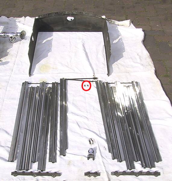
The outer shell and shutters. It is only necessary to remove the bottom pivot plates when extracting the shutters. There are two springs inside the top rail that need disconnecting after the upper pivot rails have been lowered. On this radiator one spring had rotted through.
Counting from the centre, on left and right, shutter numbers 1,3,5 & 6 will slip out of the upper guide rail when the base plates are removed; the remaining shutters are held in place by collars and split pins.
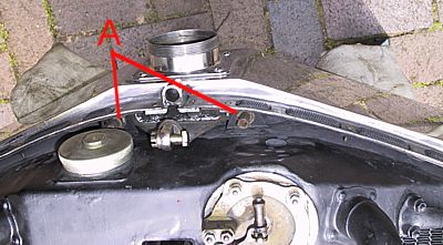
The 2 small dog-bone shaped articles circled in red are the plates that link the 2 actuating levers connected to the centre pair of shutters. Once assembled they are held in place by a nut and bolt; the latter must be removed to allow the levers to be drawn through the radiator header tank.
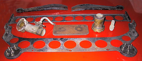
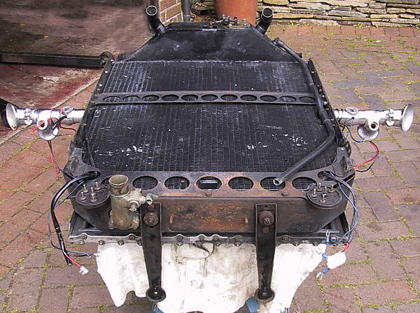
From the top :-
front shroud support brackets
centre brace
(l to r) bottom hose & drain tap; radiator spacer to achieve correct bonnet height; steam valve body; outlet tube from valve
bottom brace with electrical junction boxes.