Why play with the dip switch?
The chassis of this car has been given a re-wire in the recent past using PVC coated flex of the appropriate dimensions. The down-side is that most of the cable is black: ...invent your own adjective to describe that auto-electrician!
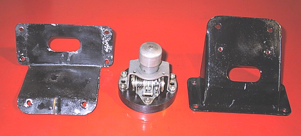
When I dismantled the engine I tagged all of the wiring to ensure correct re-assembly. Just to check, I decided to test the wiring for horn, side lights, dip beam and main beam - and dip would not work consistently. After much checking, including the equipment, I decided that the dip switch must be at fault. On the left is the switch with its two part mounting bracket.
Under the original wiring set-up the headlamps were on main beam in normal use. Dip activated a solenoid to drop the nearside reflector and extinguished the offside light completely. This method was outlawed in the UK many years ago but, when I acquired it, the car was still wired in this manner. I fitted twin filament bulbs and holders to the lamps and ran an additional wire to the dip switch to achieve double dipping (disconnecting the solenoid on the offside). This conversion also requires the running of two cross-over wires between the radiator junction boxes so that one gets both lights working on either main or dip beam. (The main beam supply runs through the nearside conduit; dip through the offside.)
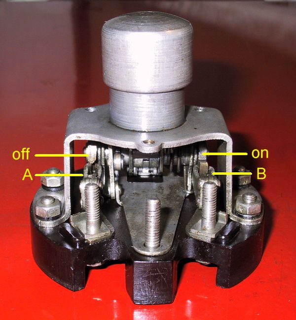
The switch used on the PIII was designed for this style of light wiring. The picture on the left shows the upper side of the switch as installed on the foot board. The cut-outs in the base plate are for cable access. The centre stud is power-in; left and right studs are for main or dip - your choice. 'A' is 'off' when 'B' is 'on' - see below.
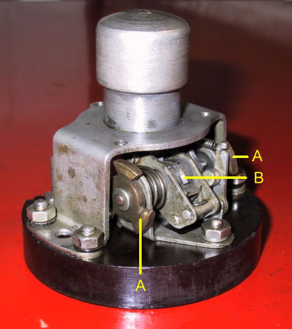
The lower side of the switch. 'B' is the ratchet that locks the spindle once the dip switch button has rotated the shaft through 60 degrees. On either end of the spindle is a notched wheel, three teeth and three notches, offset by 60 degrees. As the spindle rotates the left or right switch is engaged to illuminate main or dip beam.
The problem, stupid as it sounds, was carpet fibre built up in the contact aperture that was stopping one of the contact wheels, 'A', from rotating fully. The switch wheel was moving forward, jamming on the carpet fibres, and rolling backwards before the ratchet, 'B', could engage.
Solution: degrease, blow out with compressed air, re-oil. Put it back in the car and everything worked properly. What a pleasant way to spend an afternoon!