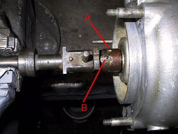
A close-up of the upper body showing how to split the shaft into two. This must be done to remove the base plate and gain access to the bearing.
Method :-
1) Gently tap the body UP the shaft, towards the cam drive cog, to allow enough room for the collar to clear the cross-pin.
2) The brass collar 'A', which holds the cross-pin in place, is peened into a machined rebate just above the notched advance plate. These indents must be drilled out to enable the collar to be slid up the outer shaft as shown here.
3) Tap out the cross-pin 'B'.
4) Withdraw the cog-shaft and base plate.
5) Tap the upper body off the inner shaft - note that there is a thin spacer sitting above the bearing.
6) Slide off the advance plate with its brass collar.

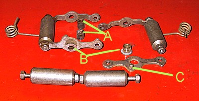
Distributor shaft components.
A) Skew gear, driven by the cross-shaft, with the small splined connection used to drive the oil pump ('A' distributor only).
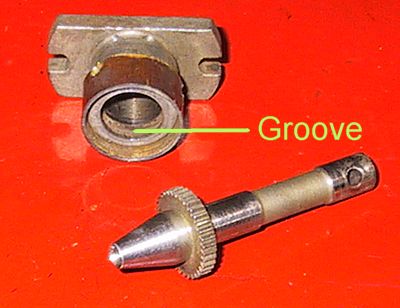
B) The upper end of the shaft is hollow and has a small oil outlet hole to lubricate the advance plate 'C'.
C) The two notches in the advance plate locate with lugs on the bob-weight levers which twist the mechanism as the weights are moved out by centrifugal force.
D) Machined element which acts as a vertical stop onto a bush in the lower body and against which the oil seal sits.
E) Small cross-pin acting as a stop for the bob-weight springs. There is no point in removing this unless it is worn.
F) Axle for the bob-weights. The portion passing through the main shaft is of increased diameter and tapered to form an interference fit. Again, there is no point in removing unless worn.
G) Elongated hole through which the cross-pin passes to retain the cog-shaft 'I'. The elongation enables the shaft 'I' to rotate, relative to the distributor shaft, to advance the ignition under the influence of the bob-weights.
H) The brass collar used to retain the small cross-pin in position; shown here pushed up to allow pin removal.