Picture #1
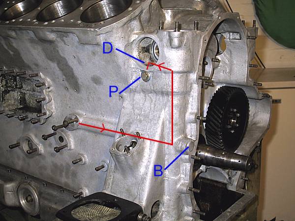
The oil supply to the timing gears and distributor drives starts at the final outlet from the oil pressure relief valve. (Oil routes will be shown in red in the all of the following pictures.)
The oil passes forwards from the low pressure relief valve into the cavity that carries the vertical oil pump drive shaft. This drilling is blanked off by the blanking plug ('B'). The vertical shaft is flooded by this supply. The reservoir of oil built up in the 'A' distributor drive chamber floods a cross-tube via drain 'D' (see picture #2). The cross-tube is blanked off on either side of the engine by threaded plugs ('P').
Picture #2
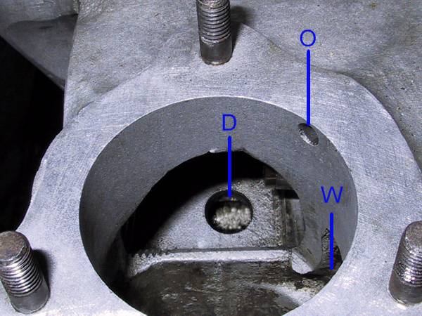
Photographed from the front and above: this is the 'A' distributor drive chamber.
Oil is pumped up the oil pump shaft housing, filling this cavity, then drains into the cross-tube (see picture #5) via the drain hole 'D'. Normal oil levels are maintained, for both distributor cavities, by the excess spilling over the weir 'W' onto the camwheel. The outlet hole, 'O', allows air pressure to remain stable by venting from or to the top of the timing chest.
It is obvious from this description that the gasket beneath the distributors need to be in good order AND that the vent holes are free from obstruction.
Picture #3 - 'A' (offside)
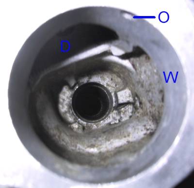
Photograph taken from the front and above.
The hole in the centre is where the oil pump drive shaft sits. 'D' is the drain hole into the cross-tube, 'O' is the air vent and 'W' the weir.
Picture #4 - 'B' (nearside)
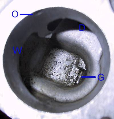
On the 'B' side it will be seen that there is no centre hole. 'O' a.nd 'W' fulfil the same purposes as on side 'A'. The hole, 'D', is an inlet hole from the cross-tube into the 'B' cavity. The gulley, 'G', is a small drilling through the casting into the oilways supplying the idler gear bush and the dynamo drive bearing (see picture #6).
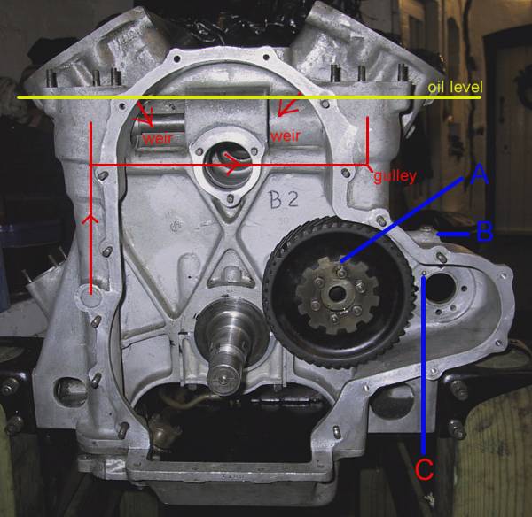
Picture #5.
The yellow oil level line denotes the top of the weir on both cavities. (It does not denote the oil level in the timing case) This picture shows the 'A' side cross-shaft spacer in place; the 'B' side spacer forms a seal at the sides of the casing for the camshaft / cross shaft spur gears. The hole in the centre is the exit for the camshaft and is sealed by the front cam bearing and its gasket.
Oil flow is from the 'A' side to 'B' via the spur gear casing, oil then filling the 'B' distributor cavity to the same level as the 'A' side. Oil leaches, under gravity, via the gulley to feed the other bearings / bushes at 'A' and 'C' (see picture #6) . The casting bulge at 'B' is drilled in both horizontal and vertical directions to create the oil passages. For some reason the vertical drilling is plugged with a bolt - which does allow access for inspection.
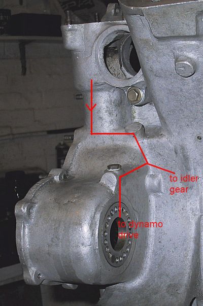
Picture #6.
Looking towards the front on the 'B' side of the engine. Oil drains from the 'B' distributor drive cavity via the gulley drilled behind the timing cover stud; its route is shown by the red lines.
The silver nut below the cross-shaft access hole is the 'B' side blanking bolt on the cross-tube oil supply.