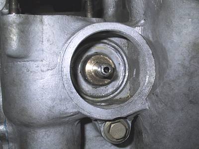
Pulled the camwheel off its taper, inserted the distributor cross-shaft from the 'B' side, engaged the gear with the camshaft gear, tapped the 'B' side spacer into its housing and re-fitted the camwheel.
IMPORTANT NOTE - the cross-shaft must be installed before the camwheel as the latter sits far enough back to obstruct the insertion if the skew gear and spacer.
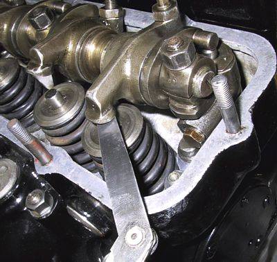
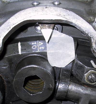
Left:- 'A' bank front rocker assembly installed with the one pushrod only. This engine has solid lifters, with the appropriate camshaft, so the flywheel is stamped '030 CLEARANCE' (hydraulic units should be stamped 020). The camwheel is rotated 180 past the A1 'open' position and the A1 inlet valve gap is set at 0.030".
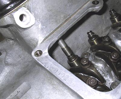
The camwheel is tightened onto the camshaft. In this instance it was set on its original keyway in the hope that the new crankshaft would be similar to the old item.
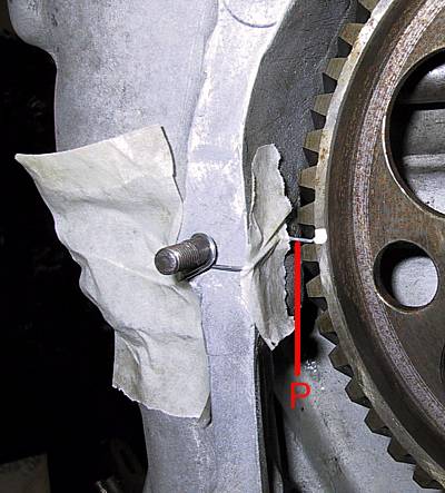
The camshaft is the rotated CLOCKWISE until the cam lobe just closes the gap on the rocker. This point can be felt by lightly rotating the pushrod - resistance being felt at the point of contact. A paperclip was bent round a convenient stud and set to point at the lower corner of a tooth root ('P'); the latter being marked with a dab of liquid paper. The camwheel and idler gear teeth were also marked where they meshed. This position of the cam now relates to the A1IO (Inlet Opens) mark on the flywheel.
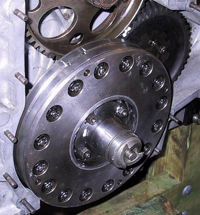
By lining up a ruler axially with the end of one tooth on the crankshaft gear it can be seen that the helical offset is roughly 2.5 teeth. The camshaft is the easier component to turn - so it is rotated backwards (anticlockwise) by 3 teeth to allow for the gear offset.
It should be remembered that the crankshaft gear is on a plain bush and that the damper, to which it is attached by springs, is to be located on the crankshaft by a taper with three keyways.
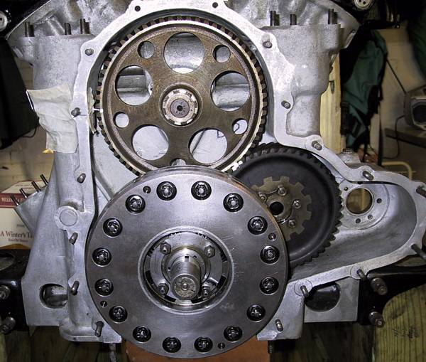
The damper keyway slots need to be aligned with the shaft keys as the unit is offered up. As the damper gear starts to mesh with the idler the camwheel must be turned clockwise to allow full engagement of the gears at the same time as locating the keys with the slots. The notch nut must be tightened up against the damper unit to ensure full and accurate engagement.
Note in this picture that the spacer ring, that fits behind the starting-handle dog / pulley spigot (not shown), is temporarily screwed onto the damper to remove any risk of accidentally separating the flywheel from the gear.
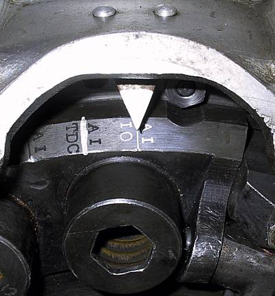
The moment of truth. From the flywheel end the flywheel is turned backwards (clockwise) by at least 1/4 turn. This part of the operation really needs two people. The flywheel is then carefully turned forwards (anticlockwise) until the A1 rocker just touched the valve stem - gauged by the other person rotating the pushrod to feel contact.
The picture shows that this engine is slightly later than the perfect position - but is within original tolerance. The 'retarded' gap is just over 5/16" (actually 0.337") which equates to slightly less than 3 degrees.
To summarise the tolerance variables for crank / cam timing:-
- the valve opening point must not be more than 0.075" (say 5/64") in advance of the A1IO mark
- the valve opening point must not be more than 0.625" (5/8") after the A1IO mark
Some useful measurements to help rectify timing that falls outside tolerance:-
- the flywheel diameter at the outer edge of the flywheel markings land is approximately 13.625" which gives a circumference of 42.81"
- there are 30 teeth on the camwheel and 15 on the crankshaft gear (the idler is irrelevant as it only transmits rotation on a tooth-for-tooth basis)
- one camwheel tooth represents 12 degrees of cam rotation or 24 degrees of crank rotation or 2.85" on the flywheel
- the offset between the two keyways for the camwheel is roughly half a tooth or 6 degrees which equates to 12 degrees or 1.42" on the flywheel
- one crank gear tooth represents 24 degrees or about 2.85"