Rolls-Royce Phantom III - water pump


Next page
Go find


R-R PIII - water pump end float  
R-R PIII - measuring w/p end float Water pump needs to be temporarily assembled to establish the amount of adjustment required to the set-screw.  The gasket is installed and the faces are tightened up to achieve a genuine reading.  The DTI on the right was set to zero with the shaft down; when the shaft was pulled up it gave a reading of 0.006" free play (ie 0.094" on the dial).End float on the shaft should be between 0.005" and 0.008".
R-R PIII - end stop

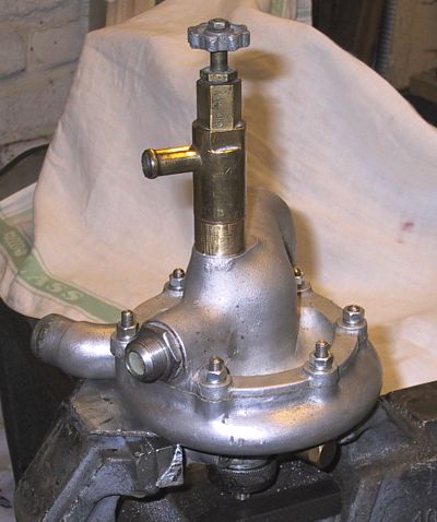
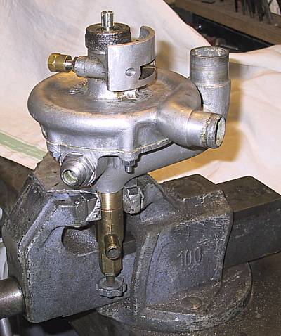
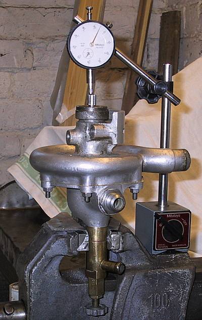
The adjustable end stop.  This one is made from an HTS bolt machined to remove the flats; this allows a socket to reach the locking nut underneath.

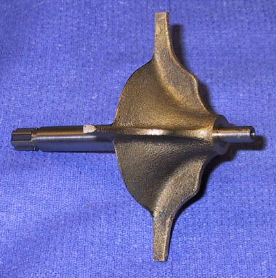
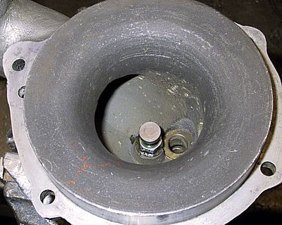
On the other half of the casting, which is second hand, somebody had machined about 0.030" off the centre boss - presumably to remove some pitting.  The upshot was that the impellor vanes were rubbing the casing.  A copper-alloy shim was made which gave roughly 0.010" clearance and was then bonded to the casting.

R-R PIII - w/p gland parts The sealing cups, etc for the gland assembly.
R-R PIII - impellor New shaft and impellor; the latter screws onto the former.
R-R PIII - water pump rear The only unfortunate matter about this casing is that the studs have been replaced using 6mm threaded rod - the excess lengths will need trimming down.  Yet another example of cretinous intervention.
R-R PIII - water pump front  


Back to the diary.
Go find
Next page