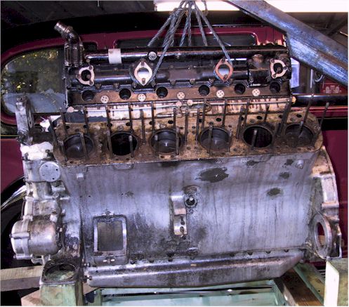
The nearside ('B') head has been removed. The front of the engine is to the left of the picture. Careful scrutiny will show that the second stud in the centre row is missing - between the first and second cylinders - this having been unscrewed to enable the head to be lifted. The awkward stud was turned by using two nuts locked together on the stud thread.
The dark dribbles on the block beneath the remaining head are the dried traces of the gasket sealant used when the engine was last re-assembled. If there is a list of 'DO NOT DO THIS' actions then gluing the cylinder head gasket must be close to the top! The sealant soaks into the top of the stud threads and is squeezed up the stud holes in the head; its affect is akin to welding the head to the block.
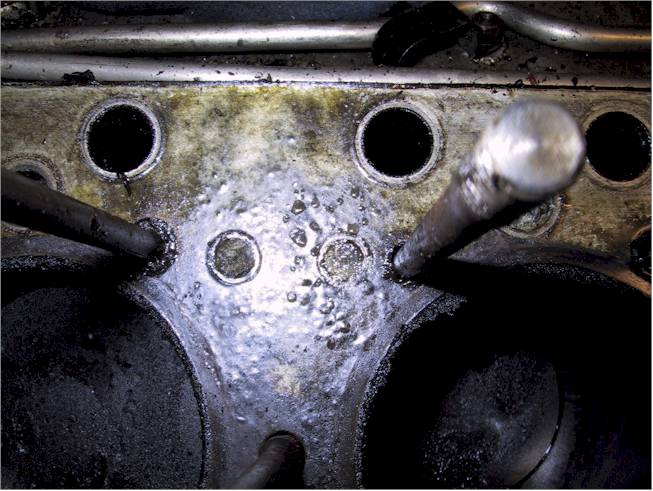
Close-up photograph of the block face. The two circles between the upper studs, and the one partly obscured on the right, are unused water passages from the block to the head. See more information on 8th March.
The brown bubbled surface on the block face is dry gasket sealant. Also note the deposit built up around the base of the studs.
On the rim of the liners is a small deposit of carbon that has expanded and softened as the diesel oil soaked under the gasket.
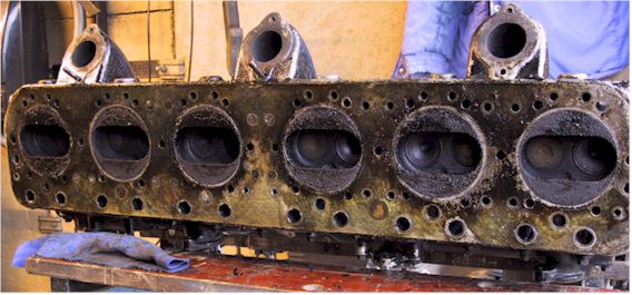
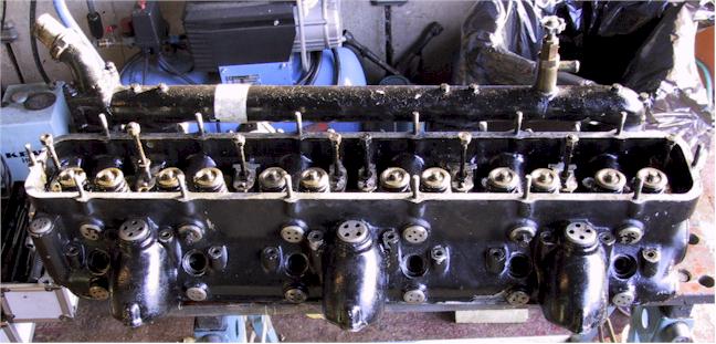
The lovely brown sheen on head mating surface is that sealant again. Inspecting the head from front (left) to rear one can see that there are fourteen unused water passages; in pairs between the combustion chambers above and below the centre stud line plus one each between the pushrod holes for #2 & #3. Although there are drillings in the block the heads are blank casting - presumably to force water to the rear of the head.
The experts will note that there are two studs in the exhaust ports. Actually of BSF thread but of an over-size. Of the 12 fixings used to attach the two exhaust manifolds only two were the correct items, the others being AF and metric bolts forced into the holes.
The valve heads are of a hollow conical form.