 The
Forgotten Engine - click the icon to find out more !
The
Forgotten Engine - click the icon to find out more !
The
Forgotten Engine - click the icon to find out more !
The diary is set out in tabular format with each day's work briefly described. If you place the cursor over the thumbnail pictures in the right hand column a message will appear stating how many pictures are available and at what size - eg "2 x images - 34&58kb". If you choose to click to the new page a narrative alongside the pictures will explain points of interest, particular problems or methods of rectification.
Click "Back to the diary" to return to this page
Click "Next page" to advance without returning to the menu
Click on the thumbnail images for full pictures
.
At some point in the dim and distant past a previous owner seems to have run the car, for a considerable period, with no inhibitor or anti-freeze in the cooling system. When the car was acquired in April 1999 the cooling system held only 4.5 gallons of water - the remaining gallon being made up of the usual sludge and hydroxide that neglected aluminium engines love to produce. Twenty-odd sessions of flushing and back flushing dislodged roughly 5 pints of the offending debris. Gano filters were fitted to the top hoses to trap any further migrating particles.
There were two results:-
First - the engine ran at between 70C and 85C (dependant on speed and ambient air temperature) - A GOOD THING !
Second - the off-side of the block started to leak - A BAD THING !
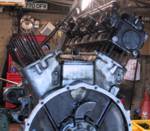
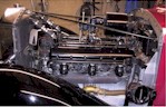
Further investigation eventually uncovered the fact that the block had been left to freeze and had cracked both sides of the engine. To 'rectify' this problem, or disguise it - a matter of interpretation - the sides of the engine had been encased in fibreglass. This had been so expertly applied, smoothed and coloured that it was indistinguishable from the aluminium. My short-term solution was to hack away the fibreglass on the off-side to expose the extent of the damage. The crack was then ground out and filled with a synthetic weld product and, for good measure, covered with a thin sheet of aluminium applied with the same compound. This produced a satisfactory repair and kept the engine continent - though not looking its best - and allowed a further season's trouble free motoring.
Knowing that the repair had not been undertaken to Henry's standards a rebuild was the only honourable answer. The following diary will hopefully show the problems, pitfalls, frustrations and eventual solution to this sorry story.
As with all jobs on old cars, one uncovers a number of obstacles left by earlier technicians ( read cretins / bodgers / idiots / criminals...add your own words). Fibreglass sheet to repair a cracked block comes pretty close to the top of my list of obstacles. During the engine removal time of 29 hours about 5 hours were wasted on several of these gifts from the past.
The usual quantity of foreign nuts and bolts - not so difficult when they are both AF or metric - but quite awkward when one item is mated or cross-threaded onto a BSF nut or bolt.
A captive bolt connecting the offside engine damper to the front engine bracket was no longer captive. The bolt head is just about accessible but the locking plate was still in place and had been bent back so that no spanner or jamming bar could be inserted. I eventually managed to insert a long drift and tap the locking plate back in to place.
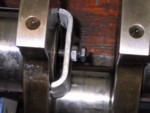
The clevis pin on the clutch fork had been pinned with a 2inch split pin which had then been bent, twisted and folded into oblivion. This clevis is right next to the gearbox and inside the cruciform of the chassis. I eventually managed to grind away both ends of the split pin using a Dremel cutter - a device that has paid for itself more times than any other tool I own.
| Date | Job | Hours | Click for pictures |
| 31st October 2001 | Disconnect battery, drain fluids. Remove and store mascot, spare wheels, bonnet, headlights, horns. Disconnect hoses, ignition leads and fuel pipes | 5 |
 |
| 1st November | Remove spotlamp, front shroud, radiator stays, wing-stay bolts into radiator. Lift and tilt radiator to access wiring junction boxes (each side of radiator bottom plate). Note wiring layout then disconnect. Remove radiator and exhaust down pipes. | 5 |
 |
| 5th November | Remove fan, coils, HT lead conduits and distributor caps. | 3.5 |
|
| 7th November | Remove the exhaust pipe and manifolds. Disconnect all remaining electrical, mechanical and gauge connections from engine. Remove clutch cotter pin, engine tie rod and brake cable anti-chatter bracket. | 5 |
|
| 8th November | Remove front engine mounts, engine friction shock absorbers, control rod link pivot (o/s/r of engine), spare wheel bracket mounting plates. Unbolt and lift off front wings. |
5.5 |
 |
| 9th November | Release engine-to-chassis stabiliser and gearbox-to-engine stabiliser. Clean front shock absorbers, drain oil and remove filler tubes - tape over the holes. Disconnect one-shot system from clutch. | 2 |
|
| 10th November | Remove short prop-shaft from between clutch and
gearbox. Remove rear engine mount and rest engine on chassis. Check that everything
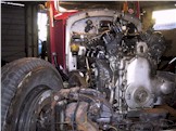
is disconnected and then... LIFT OUT THE ENGINE ! |
3.5 |
 |
| Time taken so far... | 29.5 |
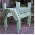
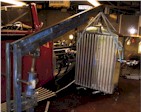
| Engine stand | |||
| Date | Job | Hours | Click for pictures |
| 12th November | Collecting timber and fixings to build the engine stand | 1 |
|
| 14thNovember | Measuring, cutting and jointing timber for engine stand | 6 |
|
| 15th November | Assemble, glue, bolt-up and stain the stand. | 3 |
|
| Time taken to build stand... | 10 |
||
| Time taken so far... | 39.5 |
Working topside |
|||
| Date | Job | Hours | Click on pictures |
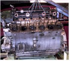
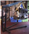
| 16th November | Lift engine into stand. Remove starter and water pump. Disconnected oil pressure relief valve, breather, oil level indicator and all fuel and water pipework from within the engine 'V'. Removed clutch end plate, top and bottom housings and release bearing. | 5 |
|
| 17th November | Extend threads on 3 off 1/2" BSF bolts for clutch compression. Compress clutch springs and remove cover, plate and flywheel. Dismantle carburettor water jackets and plinth. | 4.5 |
|
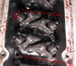
| 19th November | Remove both rocker covers and rocker shaft assemblies. (This engine has been converted to solid lifters.) Remove both sets of nuts from the head retaining studs (32 each side). Leave all studs soaking in releasing fluid. | 4 |
|
| 20th November | Unsuccessful day! Attempting to remove cylinder heads. 'A' head (off side) stuck solid. 'B' head has 1/8" vertical play. | 4 |
|
| 21st November | 'B' head removed after much effort and finally by unscrewing #2 centre row stud. Leave 'A' studs soaking in diesel oil with the engine suspended by its head - go on holiday. | 4 |
|
| 30th November | Another frustrating day! Eventually get 'A' head gasket to break free of head - 1/16" play. Seems to be held mainly by the #2 centre row stud. Funny - the same position stud that gave problems with 'B' head. | 2.5 |
|
| 1st December | You cannot be serious!!! Eventually get 1/2" vertical play at rear of head but only 1/16" at front end. Unable to unscrew stud using 2 locknuts: strip thread on stud. Stud extractor will not grip. Cut off top of stud flush with block and drill 4 off 2mm holes against side of stud and soak. Leave engine hanging by its head. | 5 |
|
| 2nd December | Blood pressure rising! Still no joy. Attempt to drill out #2 stud but the stud compound is weird and I manage only 1.5 inches. Neither hardened drills nor end-mill make any further progress. Manage to get 1/8" gap at front of head and carefully cut through the offending stud with a padsaw without damaging head or block. At last!!! Lift off second head. | 4 |
|
| 3rd December | Peel off head gaskets and clean all of the gasket sealant from around the stud bases. Soak studs in releasing fluid. | 1 |
|
| 4th December | The stud extraction saga. First attempts involved using 2 locking nuts on each stud. Stubborn studs were heated and then attacked with a stud extractor. Today's result - 52 out, 1 sawn off ,5 snapped, 6 stuck. Removed the oil supply pipes to the valve mechanism (situated in the 'V' of the block). NOTE - no washer between block and banjo. | 6 |
|
| 5th December | Studying studs. Drilled out 2 broken studs and broke 3 others whilst attempting to unscrew them. | 4.5 |
|
| 6th December | Hating studs. Attempted to drill out 3 more studs using a jig for stability. 1 success, 2 only part drilled due to extremely hard metal. | 5 |
|
| 8th December | Out or bust - the painful extraction reaches an unsatisfactory conclusion. Snapped 3 remaining studs despite best efforts at the contrary. All studs now out or broken. Attempted to drill out 2 further studs but fail due to unusually hard material. | 3.5 |
|
| 10th December | Removed notch nut from rear of crank. Inverted engine in stand: not an easy task on your own. | 3.5 |
|
| Time taken on the topside... | 56.5 |
||
| Time taken so far... | 96 |
Working sumpside |
|||
| Date | Job | Hours | Click on pictures |
| 11th December | Remove oil pump. Remove sump. 2 AF bolts forced into front corners & 1 large bolt in rear o/s corner. NOTE - ALL piston skirt slits face the thrust side - ie to the nearside. | 1.5 |
 |
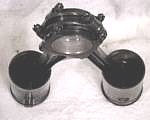
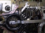
| 12th December | Measured con rod end float (this is fixed by the little end position). NOTE - forked con rods into 'B' bank, blade rods into 'A'. Removed A1 & B1 pistons. | 5 |
 |
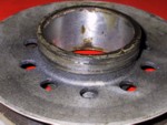
| 20th December | Removed remaining 10 pistons and con rods and re-assembled to retain relative positioning. Inspect the inside of the block and bores. | 5 |
 |
| 27th December | Removed notch nut from front of crank. Tool R2883 not available so used 'C' spanner. NOTE - right hand thread. (5 minutes) | - | |
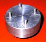
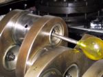
| 28th December | Tool R3168 for removal of fan pulley on crank not available. Machined blank for tool from solid bar. | 3 |
 |
| 29th December | Finished machining and threading R3168. Removed pulley (2 minutes!) | 5.5 |
 |
| 30th December | Removed timing cover. | 0.25 |
 |
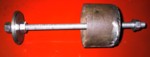
| 2nd January 2002 | HAPPY NEW YEAR. Removed starter dog from crank spigot. Removed crank damper notch nut using R2883 and crank shaft damper using R2879 - springs went all over the floor! NOTE - for no good reason the thread on the damper is left hand thread yet is only used for the extractor. |
0.75 |
 |
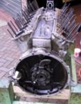
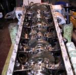
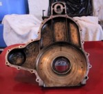
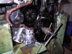
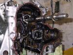
| 4th January | Removed the 2 piece crankcase end-plate
from the rear of the engine. Unbolted main bearing caps and removed bottom half of
bearings plus shims. Lifted out crank shaft and upper bearing halves. All components
are stamped to allow easy re-assembly in the correct position. 9 PICTURES |
3 |
 |
| 8th January | Removed cam wheel using R2963. NOTE - shim washer mounted on cam shaft behind wheel. Removed bush block holding the front of the camshaft. | 0.5 |
 |
| 9th January | Sorting out and manipulating pictures for web diary. (7 hours) | - | |
| 10th January | Updating diary for the last 33 days. (8 hours) | - | |
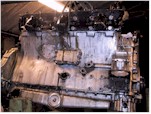
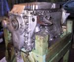
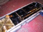
| 13th January | Decision time! Decided to hack off the blistered fibreglass on the 'B' side of the block. The thirteenth was not necessarily the best day to choose. | 1.5 |
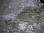 |
| Time taken on the sumpside... | 26 | ||
| Time taken so far... | 122 |
Decision time has arrived! Prior to starting this project I was aware of the possibility, even probability, that the concealed damage to the block could render the engine scrap. From the outset I made the decision to strip the engine in order to ascertain the condition of the unit as a whole; hence my leaving the removal of the filler and matting to almost last. If the internals proved to be either in good condition, or readily salvageable, then it would be sensible to repair the original block and then rebuild. The only caveat to this course of action being that the cracking of the block was limited to the water jacket and did not threaten the structural integrity of the complete assembly.
At the present date I have not taken any measurements for wear on any of the components.
Summarising the results of the operation to date:-
The location points of the head studs, particularly the 11 'A' block inserts holding broken studs, is an awkward problem to overcome. Due to the excessively hard material that some of these broken studs were made from it will probably be necessary to remove them by either acid etching or spark erosion - either of which will damage the existing inserts. It is not known whether the larger inserts have breached the water jacked.
B2 piston is damaged and will need replacing.
A1 liner is chipped inside and has a piece missing from its skirt. The need to extract this liner may damage the block.
The big end bearing shells are worn and the white metal on the bearing blocks for the blade con rods is breaking down.
The crankshaft is showing minor signs that previous regrinding has breached the case hardening. In itself this is not a problem but the crankshaft may not be accurately aligned in the block as displayed by the wear in the rear oil screw housing.
There is evidence that the liner 'O' rings are leaking.
The water galleries are still partly choked with rubbish. The best way to overcome this would obviously be to remove the liners and clean the whole area completely. This would also allow for a better repair of the cracks.
The block sides are severely damaged although it does not appear to have compromised the integrity of the assembly.
Final strip down |
|||
| Date | Job | Hours | Click on pictures |
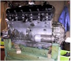
| 24th January | Well it's some good news, some bad news and some more good news. The first bit of good news is that I have found a replacement block. The bad news is that I have spent all of my beer money for the foreseeable future. The really good news is that the replacement block has been stripped, cleaned and pressure tested. It also comes with its own sump pan, timing cover and crankshaft. It has both original heads - also stripped and pressure tested - plus a brand new set of liners, seals, pistons and rings. | - |
 |
| 28th January | Still on the old engine. Made castellated box spanner.
Removed dynamo drive. Made jamming bar for idler gear then removed it.
Nb - the nut is left hand thread. New engine. Removed the sump, crank main bearings and crankshaft. |
6 |
 |
| 29th January | Old engine. Turned engine the right way up in the stand - much easier now most parts are removed. Removed both cam cover plates and the six cam follower blocks. Started making a tool for removing the core plugs from the cross-shaft distributor drive. | 3 |
 |
| 30th January | Old engine. Completed the core plug extractor and removed the plugs. As usual, 1 1/2 hours to make the tool and less then five minutes to remove the two plugs. | 2 |
 |
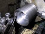
| 31st January | Made an extractor for removing the cylinder liners. Old engine. Spent ages working out how the cross-shaft assembly is to be removed - decided to find out if my conclusions were correct before proceeding. Tried to remove the broken A1 liner but it would not budge New engine. Removed B1 liner for the hell of it. All liners will be replaced anyway. |
6 |
 |
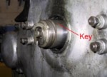
| 2nd February | Removed distributor drive cross-shaft. Click on the picture to find out the secret. | 0.5 |
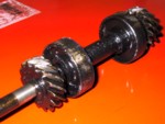 |
| Same day | Removed camshaft. | 1 |
 |
| 4th February | Set-up de-greasing tank. Measured old and replacement crankshafts to ascertain amounts of wear. Decision needed on which to use. | 5 | Wear tables |
| 5th February | Cleaning starts! Cleaned crank end plates plus odds and sods. Started to remove the sludge traps from the old crankshaft - 6 big ends and 3 of the mains. | 4.5 |
 |
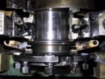
| 6th February | The pragmatist's puller - made an extractor to remove the more stubborn main bearing sludge trap caps. Removed the caps and cleaned out the crankshaft. Started cleaning the trap caps. | 6 |
 |
| 7th February | Continued cleaning the sludge trap end caps until my Dremel burned out. Started work on the other engine. | 1 | |
| Time taken on the last stages... | 35 | ||
| Time taken so far... | 157 |